Forging Norse Trefoil Arrowheads
Author: Darrell Markewitz
Note : Modern industrial stock was used as the raw material. Sizes for this (and much of the forging process) are given in Imperial measurements.
Artifact Source
There are at least two (
1) unusual arrow heads illustrated in James Graham-Campbell - 'Viking Artifacts'. These are described as his number 12 (part of a group) and 267 (two shown) , " ... from the large find discovered in Estuna churchyard in 1964. ... objects of 7th to 11th century date are 245 arrowheads ... the greater part dating to the Viking Period." (pg 12)
From : Estuna, Uppland, Sweden, listed as Statens Historiska Museum 27761 (both images).
Further details are given on the second entry #267:
"Two tanged iron arrow-heads, with trefoil-sectioned blades of pointed oval form : between the blade and the tang is a rounded shaft, the larger having two ornamental mouldings. L 15.7 and 11.3 cm." (pg 74)
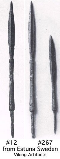
Scan from 'Viking Artifacts' - modified to life size
Deciphering fine details of an artifact from photographs is always difficult - especially when only a single image is available. Despite the small size of the objects, they do appear in extremely good condition, so proportions and exact measurements can be established. The exact cross section of the arrowheads is not given, other than as trefoil - having three edges. The images show this basically as a wide triangle, the longest side being more or less flat, with the third point forming a shallow peak down the centre line. Some indication of the relative cross section shape and width to thickness would have been extremely valuable (!).
Functional Considerations
There is a strictly military implication for a triangular cutting head on any piercing weapon. In simplest terms - a three sided cut is difficult to hold closed, and thus is more prone to infection, and makes for difficult healing. This (somewhat grisly) factor has to be remembered when assessing the greater difficulty in forging this shape compared to the more common diamond cross section arrowhead.
There are two methods for securing an arrow head to its wooden shaft. There are functional reasons why arrowheads intended for military use (especially pitched battles) are designed differently than those primarily for hunting purposes. (
2)
The ideal way to manufacture a head for a hunting arrow is using a conical socket at its base. This provides the most secure attachment to the wooden shaft. It also results in the least amount of damaging stress applied to the top of this wooden shaft at impact. The conical shape distributes the impact force over the widest possible area. If anything, the conical shape acts to compress the wood grain, rather than attempt to split it apart. The arrowhead is most likely to remain fixed to the shaft on any attempt at extraction. (This somewhat dependent on blade shape and additional method of attachment to the arrow shaft - use of glue for example). At the same time, arrowheads with conical sockets are considerably difficult to make, requiring specialized tools, considerable skill - and certainly more raw time per object to complete. This results in an arrow with multiple 'shot' uses.
Forging an arrowhead with a wide flat tang is certainly very quick. The method of attachment then is to cut out a narrow slot into the end of the wooden shaft to receive this tang. There then needs to be a binding applied of cord or sinew, to keep the head aligned straight and well attached to the shaft. On impact, the force will be directed down the tang, which will act like a wedge on the wooden shaft, attempting to splinter the grain. (This effect is somewhat mitigated by the reinforcing of the binding.) If the arrow head remains attached, the arrow can be re-shot. There is a good chance that the shaft will be damaged beyond use after a single impact however.
An arrow with a slender conical tang is slightly more difficult to forge than the flat tang - but certainly much easier than the full socket. (It also uses the least amount of material per arrow, which may also be a consideration.)
The tip of the wooden shaft is prepared by drilling or burning out a small hole of a size to fit the tang. As the head's tang is conical, mounting a head means only tapping one into place. It is important that the shoulder area between the tang base and the head's shaft be as close to flat and square as possible. On impact, this flat area distributes the impact force over the surface of the end grain of the wooden shaft, resulting in the least potential damage to the shaft itself. Importantly, because of the conical shape of the tang, the arrowhead is most likely to simply pull free out of the shaft on any attempt at extraction, especially if embedded in a hard or gripping material. An added 'bonus' is on impact into flesh, where most likely the head will be left behind, increasing the damage caused. The most important overall effect however is that arrows with cylindrical tangs are 'fire and forget' - in a longer battle they are not able to be return launched by the opposing force, but can easily be recovered at battle's end and new heads installed.
Although the sample is only two heads, the close similarity in size and shape to the two conical tangs certainly suggests the kind of relative standardization that would be required for the system given.
Forging Methods
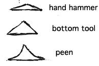
There are three different forging methods that could have been used to create this triangular shape of the blades. Each results in a slightly different cross section. Each has its own tool / method problems.
A) Forge from starting stock into a blade shape, but only hammering one side of the starting bar. This is likely to produce a relatively wide blade, with a fairly shallow central rib. The central line is more likely to waver (the result of many individual hand strokes). No special tooling is required to accomplish this, although there is a high degree of hand skill involved when forging this shape at such a small scale. Even still, there may be considerable variation between individual arrowheads.
B) Forge starting stock into a special bottom tool, hammering from one side of the bar down into the form. This is most likely to result in a very pronounced central rib, with a crisp line. The exact profile of the bottom tool used will determine the exact shape of the resulting arrow head. The individual arrowheads are going to be quite uniform when compared to each other. This method is the fastest when the smith is faced with producing a large number of arrowheads (as would be expected in a military situation). It does require the creation of a specialized forming tool.
C) Forge starting stock using the cross peen side of the hammer to forge a shallow grove on each side of the blade. With great control, it might be possible to align multiple individual strokes to accomplish this. More likely this would be a task using two workers. The cross peen would be used as a top tool, held by one while a second directed blows onto the face of this hammer. This will produce a curved cross section - the curvature of the two grooves dependent on the shape of the actual hammer peen. It may prove difficult to produce a smooth shape, with a certain amount of waver to the central line. There can be expected to be variation between individual objects.
�
Potential cross sections - by method
Without better examination of the source artifacts, some guess work based primarily on the dynamics of production are perhaps the best guide to the actual method employed.
Method B, use of a bottom tool, is most certainly the fastest way to produce a standardized object.
A second consideration is the method chosen to create the transition from base of the shaft to the tang.
It is possible to create the 'necked' shape by positioning the bar over the rear edge of the anvil. Then striking the metal with the cross peen of the hammer, very carefully positioning each stoke so the peen aligns exactly with the anvil edge. It can be extremely difficult to get each of the repeated hammer strokes required in exactly the same position - even for a skilled worker.
A quicker (and generally more uniform) method is to use a 'shouldering tool'. This can be simply and quickly formed by creating a length of round cross section stock, with a flattened section in the middle. This is then forged around to a very shallow U shape. In use the metal to be formed is inserted into the end arms of the U (which is held horizontal on the anvil surface) and the hammer strikes the top arm just above the working bar. Generally after a first impression, the bar is rotated 90 degrees for a second compression. After this the bar is presented 'edge up', with four more strikes converting square grove to octagonal. This is followed up by a series of small rotations and lighter taps to create the cylindrical shape desired. The remaining material 'downstream' of the shoulder is then forged out to the slightly conical tang.
Either method however, results in a rounded shape at the transition from the tang to the main shaft of the arrowhead.
As described under 'Functional Considerations', it is less than ideal to have a rounded shoulder at the base of the tang. This area should be flat and have the tang junction at a crisp 90 degrees to the shaft.
One way to accomplish this flat surface and sharp edge might be to take the forged shoulder as described, then refine the shapes with a file.
If the two artifact heads are examined closely, it it in fact looks if the base of each shaft is widened, possibly the effect of upsetting the base of the shaft. This would be accomplished by first forging the shoulder and tapered tang on one end of a longer rod as the start of the process. Then this tang would be inserted into a block with a small hole driven into it, ideally with a matching taper. The heat on the bar is carefully controlled, limiting the heat to just above the shaft base. On insertion, the bar is hammered sharply on its other end. The net result is to drive the base of the shaft downwards, which compresses the rounded shoulder into a crisp and flat transitional shape. The metal just above the block will slump and expand outwards (upsetting), resulting in a shape much like what is seen on the artifacts.
Once again, careful examination of the iron grain pattern on original objects would leave diagnostic signs of either method being used.
Arrowhead #12 (left side images) also has a feature which suggests it was not part of a large mass production. This is the small grove placed into the bottom end of the actual blade. This certainly adds extra time in production, and is only a decorative element. If anything, it potentially reduces the effectiveness of the arrowhead, in that it creates two slightly pinched lines into the shaft, each potential weak areas which might promote bending on impact.
There are two ways this might be done:
a) run the corner edge of a small file over the completed forging, cutting a pair of cylindrical grooves into the metal. This would be relatively quick, but does remove some of the parent metal.
b) forge or cold strike a shallow cut using a chisel, rotating the shaft as individual cuts are made. This might prove a bit difficult to control, in terms of cutting to a uniform depth.
The effect of ether of these methods might be determined by closely examining the grain structure of the iron metal in the artifacts. Filing a groove will cut the grain lines, striking with a chisel will compress them.
On Production
Modern mild steel bar stock was the material, with profiles as indicated under the individual descriptions. Actual bloomery iron would have a pronounced grain structure, not likely to be a major difference (save as diagnostic marks as discussed). Bloomery iron is considerably softer, so would likely have allowed the shaping process to proceed more quickly. Depending on the actual carbon content measured in the artifacts, there might not be any hardening processes employed originally. Although modern mild steel can be slightly quench hardened, no special attempt was made to utilize this process in the samples.
Metal was heated using a propane gas forge. For objects in this size range, there would be no significant difference between this heat source and a Viking Age charcoal fired forge and bellows combination. (The bellows would have best required an assistant, and if anything, more precise heat control would have been possible with the more ancient equipment.)
A modern large (225 lbs) anvil was employed. The primary effect here was the use of accessory tools (as discussed under Forging Methods) equipped with square mounting shafts so they would fit to the anvil. Although this large anvil is certainly more stable than the small Norse anvils (examples in the 10 - 15 kg range), for forging such small objects this advantage is not deemed significant.
The primary forging hammer was 800 gm and round faced, this differs from Norse artifacts in that these are all square faced. This is considered not to be significant, and reflects personal choice only.
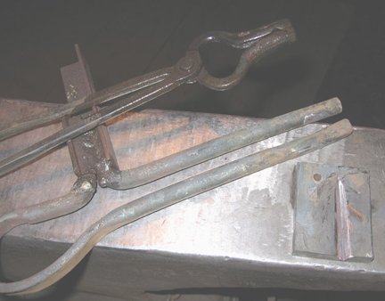
Tongs / Shoulder Tool / Bottom Tool
The shop is equipped with a slender pair of grooved 'bolt jaw' tongs, intended for working small diameter square or round stocks. Arch jawed tongs are found in Norse context, although generally heavier in construction (and thus better suited to heavier work). (
3)
The shouldering tool used is standard equipment, common to most traditional or modern blacksmith shops. In this case formed of 1/2 round stock. It should be noted that no such tools have been noted in a Norse context. (
4)
The simple bottom die tool was created from a small piece of heavy flat stock - 5 x 1.2 cm by 6.5 cm. (2 x 1/2 inch stock)
a) The hole used for the upsetting process was created using a 3/16 inch bit on a modern drill press. Tools equipped with multiple holes of various sizes and taper profiles are known from the Viking Age. These are equipped with short handles to allow for hand control (Norse anvils are not equipped with modern style square 'hardie' holes!). (
5)
b) A tapering triangular cross section depression was created in the block, running from one side. The total length was 5.5 cm, descending to 1 cm wide by roughly .5 cm at its deepest. This was formed by first creating a pattern piece, 3/8 inch square stock was forged out to a square tapered point. The block was then heated to a 'bright orange', and placed on the anvil. The taped pattern was placed across the block, diagonal edge up. This was then stuck with the hammer, driving the pattern down to create the triangular impression into the block. This process was marred by a double imprint, which was cleaned up slightly buy using a grinding bit (work also easily done with a file or stone - just not as quickly!)
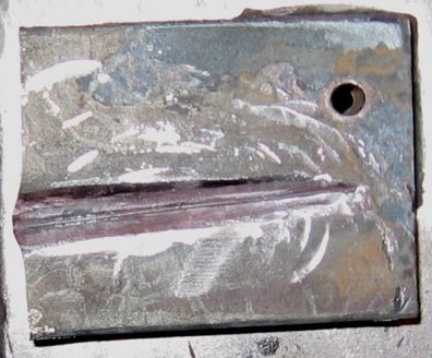
Trefoil bottom tool (enlarged)
It should be noted that no attempt was made to precisely duplicate the individual artifact samples. The intent of the project was to investigate forging methods. The results are considered to be 'of a type', rather than exact reproductions.
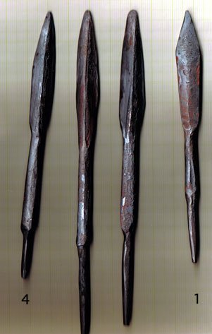
The Samples
�
A total of four arrowheads were produced:
Numbers 1 & 4 most closely resemble Artifact 256.
Numbers 2 & 3 most closely resemble Artifact 12.
Number 1 - was made from 1/4 inch round stock:
- forged to a tapered square point
- laid on flat edge, then hammered to a 'double bevel' on one side only
- necked in slightly on edge of anvil, at base of blade
- drawn to slight taper on shaft just below blade
- cut from source bar
- shouldered with tool at base end
- drawn as tapered point from shoulder for tang
Number 2 - was made from 3/8 inch square stock:
- first forged down to roughly 5/16 inch square
- forged to tapered point
- blade formed by compressing on the edge into the die
- initial forging revealed irregularities in the die, these were ground smooth, then a second compression step was added (some faint marks remain on left)
- square shaft was re-profiled to cylindrical
- shaft forged with slight taper to base of blade
- cut from source bar
- shouldered with tool at base end
- drawn as tapered point from shoulder for tang
Number 3 - was made from 1/4 inch round stock
- shouldered with tool at base end
- drawn as tapered point from shoulder for tang
- tang inserted into block and upset to square shoulder
- cut from source bar
- forged to tapered point
- blade formed by compressing on the edge into the die
- shaft forged with slight taper to base of blade
Number 4 - was made from 1/4 square stock
- forged to tapered point
- blade formed by compressing on the edge into the die
- shaft forged with slight taper to base of blade
- shaft forged with slight taper to base of blade
- cut from source bar
- shouldered with tool at base end
- drawn as tapered point from shoulder for tang
Conclusions
Modification of the shouldering tools used might improve tang to shaft forming part of the process. Creating such a tool out of smaller 3/8 diameter stock would have served to reduce the resulting radius, speeding the final upsetting process.
It might also prove feasible to create a specific shouldering tool out of square profile stock. More care would have to be undertaken in alignment, but a much more crisp corner to the base of the tang initially would be the result.
The step of upsetting the tang base into a block certainly makes for a crisp shoulder, and creates the indicated upset width at the base of the shaft. Correct estimation of the required diameter to fit the hole in the block is required for the upsetting process Getting just the correct fit took several attempts, as this step was only undertaken once in this series. Continued practice would speed this considerably.
Using this method does require that the tang end be forged first.
Considering object measurements against production ease, the most effective starting stock size, (with modern materials) is 1/4 inch round. Some advantage can be gained by using the slightly more massive 1/4 inch square, in terms of producing a slightly thicker central rib on the blade. This needs be balanced against the slightly more work involved in forging the shaft down to cylindrical. One consideration in terms of historic practice would be the time and effort involved in converting the source currency bars (roughly 2 cm square) down to the equivalent of those convenient starting stock sizes.
For this series of four, including the creation of the shaping / upsetting block, the total time was two hours. It is hard to break that down to 'time to object', as with any prototype generation, there is considerable misstep along with effective working. A 'best guess' is roughly 10 - 12 'heats' per arrowhead. Likely with two objects in production at once, this suggests a production rate of roughly 10 minutes each, perhaps less with consistent practice.
There is no reason for creating arrowheads using a triangular profile - other than the additional damage they are certain to inflict to a human target. There is potentially some extra rigidity to a triangular spine. Making a square cross section bodkin point is so much faster - and has both better penetration and strength. It might be considered that despite the effort involved in making trefoil heads, they combine the wide cutting of the simple broad head with the added rigidity of the bodkin, with increased damage to target potential.
The rarity of the trefoil head suggests that for most Viking Age weapons makers, producing this type was just not worth the extra trouble involved.
Notes
(1) When the two separate photographs are merged (#12 on pg 186 and #267 on pg 251) It would certainly appear that the longer of the two trefoils is actually illustrated in both photographs. The fine details (as best can be determined from a single photograph) are virtually identical. For purposes of this project, I have decided to proceed on that basis. (
back)
(2) This information gathered during a long private conversation with an archaeologist / experimenter from the Royal Armoury, Leeds England, which took place at the International Congress on Medieval Studies, Kalamazoo USA in 2013. (
back)
(3) A specialist arrowhead maker might certainly 'invest' in the specific tools described as used in this project. Many light weight tongs are known, although most of these where more likely to be used for jewelry / fine metalworking (even smaller than those used here). Two heavier 'arch jaw' tongs were found with the Mastermyr Tool Chest. (
back)
(4) The lack of a specific tool of this type does not necessarily preclude its use. This is a simple construction, with little of the needed bar physically shaped. It is quite reasonable that if not needed, any such tool could have quickly been re-forged straight to serve as raw material for other objects. (
back)
(5) One of the best known of these from the Mastermyr Tool Chest, object #86. Although this is described as a 'nail making iron', it bears conical holes, not tapered square cross sections, as would be required for making nails. It may have been functional for creating heads on rivets for ship construction (normally cylindrical shafts). It also would be idea for the kind of upsetting process used in this process. Although the Mastermyr tool has holes of far too large diameter for making arrowheads, the same upsetting to square shoulder method can be used for the mortice and tendon joining technique. (
back)
References
Arwidsson & Berg - 'The Mastermyr Find', Almqvist & Wiksell, 1983
Cole - 'Hector Cole - Arrowsmith',
http://www.hectorcoleironwork.com/Arrowheads.html, accessed 2014
Graham-Campbell - 'Viking Artifacts', British Museum, 1980
 Dark Ages Re-Creation Company